|
 DvC1-02 (Hollywood Quarry "Objects vs Layers") DvC1-02 (Hollywood Quarry "Objects vs Layers")
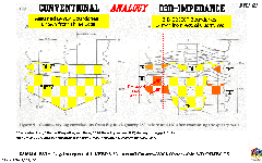
Figure DvC1-02 shows, using "well logs" of (visible) outcropping rocks, the conceptual differences between the relatively simple, layered-earth model and a more complicated object-filled-earth model. It is based on the D3D-profound-results of a geological experiment conducted in the Big Rock Quarry, near Hollywood, Arkansas (Jordan, Slatt, Gillespie, D'Agostino, and Stone, 1993). Jordan, et al, used Geiger counters to measure and record the natural gamma radiation of the quarry wall's outcropping rocks. These measurements were taken along numerous, widely separated (tens of meters), vertical tracks from the top to the bottom of the quarry wall. The subsequent curves showing "radioactive counts versus vertical distance", from some datum elevation, simulating a set of subsurface gamma ray logs, often run in the millions of wells drilled by petroleum-seeking companies all over the U.S. Organic materials in shale-bearing rocks emit more natural "gamma ray" radioactivity than do clean (quartz, in this case) sandstones, and so are seen as high-count kicks-to-the-right on the vertically displayed graph, or log curve.
Panel A (on the left) shows how an experienced geologist, in a blind experiment, interpreted three neighboring gamma ray traces, correlating two yellow sand facies (layers) interpreted on all three log curves, in tracks (or simulated wells) #3, #2, and #1, from left to right. A petroleum industry conventional assumption might be that these sandstones could form more-or-less homogeneous reservoir units, unless they are disrupted by permeability barriers, formed by faulting or other observed structural effects, such as gradual facies changes and unconformable erosion surfaces, etc. If we bound these layers (by opposing dip or permeability barriers) in and out of the plane of this section, tilt them up, charge them with buoyant hydrocarbons, and block the petroleum's up-dip escape route, we have created a classic, much-sought-after Prospective Trap. Note the absence of interpreted internal character within the two yellow "layers". A standard layered-earth model Prospective Trap does not usually warrant such detailed and speculative (based on widely spaced logs) interpretations.
Panel B (on the right) shows the same three gamma ray logs (actually Geiger counter graphs), this time interpreted after the same geologist studied the actual rocks in the quarry wall. Note that the two yellow sands, interpreted to be present on all three logs, now have become seven separate sands: three orange ones only seen by Well #3, the two yellow ones found only in Well #2, and two more orange ones seen only by Well #1. One can still see the layered-earth model's influence on the geologist, in the lateral extension of each sand body. But inspecting the quarry wall is here unapologetically proposed to be analogous to inspecting a seismic D3DSP-impedance volume, with its object-filled-earth model used to interpret log curves, viewable using a D3D-workstation project. That is, both the visual inspection of a quarry wall and the D3DSP provide high resolution detail, almost to the point of creating an abnormally high frequency, some would say "noisy", geologic cross-section. In this Figure, the vertical dashed line will be referenced later, as a proposed "noisy geology" solution to the (layered) problem presented by a water-drive reservoir, discovered (probably) up-dip to, and produced and abandoned approximately twenty-years prior to, the (probably) down-dip, high-volume, water-free discovery well, at Eugene Island Block 27. This is a good example of “noisy” (but highly prospective) geology.
|

