|
 DvC1-05 (D3D vs DMO vs Streamer Cross-sections) DvC1-05 (D3D vs DMO vs Streamer Cross-sections)
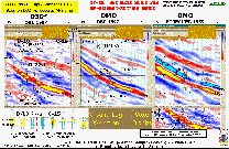
Figure DvC1-05, unlike the previous cross-section, is not taken from an exposed quarry wall, but is a working example of a layered-earth model ... of the middle Miocene (CRIS K, deltaic) "O" sand at the South Timbalier Block 26 oil and gas field, shown on the Figure DvC1-04 index map. Its surface track location is shown on the (layered assumptions) geological facies map in Figure DvC1-06. Shell Oil discovered this highly commercial, high gas-oil-ratio (GOR), depletion-drive ST-26 field, in 1968, just south of the southern edge of the previously documented Bay Marchand salt diapir (Abriel, Neale, Tissue, and Wright, 1991, Modern technology in an old area: Bay Marchand revisited: THE LEADING EDGE, 10, no. 06, 21-35). EPL purchased this mature field in 1998, partnered with Unocal (now Spirit 76 Energy), and purchased a license to 54 square miles of speculative, multi-client, ocean-bottom-cable ("spec OBC") 3-D seismic data. In the lower left-hand corner of this Figure, is a north-south log cross-section connecting nine logged Shell wells, and EPL’s D-22ST side-tracked well, drilled (in 1999) into a previously interpreted "poor quality reservoir sand" area (that is, colored blue on the log cross-section), with its bottom hole position based on some good development engineering and geology, along with the D3D-impedance line shown on the left.
The up-dip D-10 well was completed in March 1970 and shut-in as a secondary gas cap well. It never produced, and was therefore presumed to be gas charged when the seismic survey was acquired. The down-dip C-15 well was originally logged and interpreted to contain 117-feet of net oil sand, and had already produced 2.7 mmboe (million barrels of oil, and gas equivalent) to date, starting in December, 1973. It was beginning to make appreciable water along with its decreasing oil and gas. The dual goal for this first drilling operation, the D-22st, was to locate the moving gas-water-contact (GWC), and to perforate the oil leg just above the oil-water-contact (OWC) in this area. The D-22st was planned to substitute for the C-15 when the C-15 finally "watered out", and then continue production until the oil rim was completely produced. The plan was to let down-dip water injection push the OWC up, while natural gas-cap expansion would push the GWC down, keeping the D-22st in an optimum producing position until the last drop of oil had been recovered. At least, that was the plan, as designed by the engineers.
The D-10 and C-15 wells are also highlighted in this Figure DvC1-05, and the interpreted dual lobes (B and C members) in the D-10, plus the single massive C-member lobe in the C-15, can be seen clearly on both the log cross-section and on the high-resolution D3D-impedance line (upper-left panel in this Figure DvC1-05).
|

